Background
I started working on this project *3* years ago. I had the idea, worked on it a few evenings per year, and put it aside.
This year has not sparked much joy. I had Christmas week off. I spent my Christmas week off getting it done! It took a week.
Yes you can buy a bigger and multicolor display at Adafruit. For less than I paid to buy parts and build this!
Yes you can download drivers and example code (like the Adafruit_GFX libraries) and get going in no time on that display you bought.
But the fun is in the journey and I wanted to build it all myself, from designing and assembling the display down to the bare metal device drivers. It made me happy, and the debugging was fun.
I did borrow the fonts from the MD_MAX72xx LED Matrix Arduino Library, because making fonts is not fun (but bitmaps are!). The MD_MAX72XX library just linked to is the most complete and fully featured MAX7219 library out there. Just use it and the examples, do not try to start with my code!
Quick Overview of the Finished Product
I had played with the MAX7219 based display boards for years. The MAX7219 can drive a single 8×8 LED display matrix or 8 7-segment LED displays. The integrated chip and display on a printed circuit board can be purchased as a single unit. A PCB with 4 daisy chained units can be commonly purchased as well, creating an 8×32 display. Tutorials abound online on how to program these displays. See examples such as here and here. And there are seeming dozens of libraries as well.
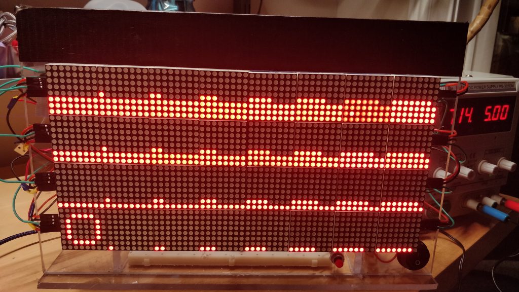
Physical Display. This display is comprised of 8 8×32 boards, each having 4 8×8 displays daisy-chained together. It is driven by the SPI bus, and data loaded into the first device in the chain shifts data from that device to the next device down the chain, and so on. Each row is 2 8×32 boards, and I desoldered the edge connectors and used a combination of soldering and wiring (to fix mistakes) to create a single 8×64 row. I created 4 such rows. Those rows were then aligned, lots of measuring occurred, and I drilled mounting holes in piece of 1/4″ polycarbonate. The displays were mounted with screws and standoffs. Additional pieces of polycarbonate were cut and glued to make the device freestanding. The base has a reassembled set of breadboards for circuit prototyping and the microcontroller, and the backside of the display has additional “buses” from breadboards for power distribution and easy interconnects.
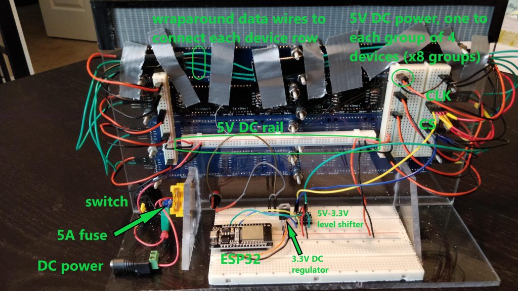
Electrical Connections. The online tutorials make this look easy. 5 wires between your display and an Arduino, connect to your computer, and you are done! That works with an 8×32 display. And your computer’s USB port can (usually) source enough current to power it. But this larger display will pull 4A of current when fully lit! I needed wires with more gauge than the typical 28 gauge Dupont connector wires these kits comes with. I purchased a kit to crimp my own Dupont cables to make my own connectors, this also allowed neater wiring and a better physical setup, and I could crimp them to solid core 22 gauge hookup wire, which could handle the currents. The power to the device has a 5A fuse and is 18 gauge wire to the “DC bus.” Rather than daisy chaining the devices for power, there are 8 5VCD and GND connections, one to the connector for each of the 8 8×32 displays. To reduce noise and crosstalk problems, the CLK and CS lines were not daisy-chained but driven in parallel to each row. The DIN lines wrapping each row to the next had to be separated from all the other wires and had GND lines placed between each, also to reduce noise problems and enable the SPI bus to run at 10 MHz (without these mods, it was running at 300 kHz …). There is a standard 2.1mm DC power connector and it is driven by a 6A 5V power supply or a benchtop power supply. The breadboard has an ESP32 microcontroller, a 3.3V regulator for powering the ESP32, and a 3.3V to 5V level shifter.
Software. I wrote device-level libraries that facilitate register level programming of the 7219 devices over the SPI bus. They make it easy to send commands to all the devices or just target a single device in the display matrix. The demo code testing out all of these features, which I also used for determining display orientation and alignment (which dot is driven by which register, left/right and up/down). A video of my code running and testing these drivers is below. I then write display-level drivers that build on these libraries and enable common features to treat it like one integrated display, such as drawing bitmaps, writing text, drawing lines and boxes, etc. A video testing these routines is also below. I learned how to fight the Arduino IDE into using many C/C++ and header files and have them included and compiled the way they should be.
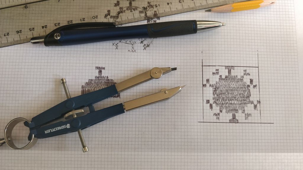
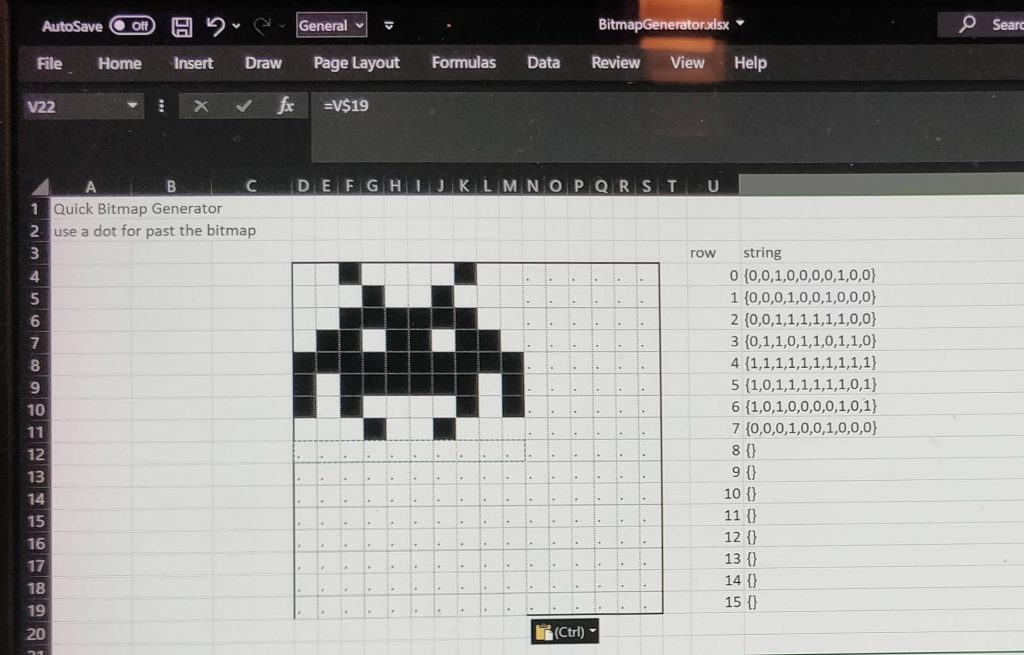
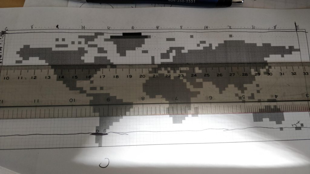
Bitmap Design. Besides writing lots of code at various levels (from display routines to hardware level writing), bitmaps play a major role. Besides drawing the bitmaps, each had to be translated into a long list of 1s and 0s. For small bitmaps, I created an Excel spreadsheet to play with different designs and generate the data I could copy into an array in my code. For medium sized bitmaps, I designed by hand (like the Pacman ghost and the covid particle) from online pictures. For really large bitmaps like the world map and Atlanta skyline, I imported an image or map into Inkscaped, created another layer with a grid, then placed semitransparent boxes snapped to the grid over the image. There is a bit of an art to this — sometimes the best looking result is not a simple mapping of the image to a dot or no dot, the low resolution means that sometimes key features need to be captured to look real. This was reminiscent of my Lego Globe that I built over 20 years ago, where I dealt with similar tradeoffs. Some pictures are below.