
More details forthcoming.
Notes: 2N3904 transistors were replaced by ones with a much lower VCE voltage. The 220uF decoupling capacitor is critical to avoid odd slow powerup oscillations (likely due to relay inductance).
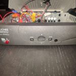
The enclosure is a Hughes SatTV box I bought at a thrift store for #1, tossed the board, and saved the power supply for a future project.
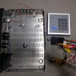
What this does: allows an RFID reader to switch the power on a 12V power supply that sources about 20A. An automotive relay is used to switch the output of the power supply. They keypad activates the relay, and the relay uses a latch configuration to keep the relay on after they keypad output goes low again.
This would be a very simple circuit if not for the fact that the keypad has a power-on glitch (output is activated for about a second), and the power supply whose output is switched is also used to power the keypad! The solution is to have two transistors in series switch the relay switch — one transistor is controlled by the keypad, the other by a 555 timer circuit that does not go high until about 7 seconds after power is turned on.
Finally, the switched output is also tied to a 12V automotive indicator lamp, to remind users that the power supply is on. The entire system is turned off by just turning off the power supply.
-
- SatTV box from thrift store, $12 keypad, $2 automotive relay, custom timer board
-
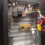
- Repurpose PCB holes to secure ckt board and relay
-
- I added a 12V auto light. An indicator that the relay is active is really useful.
-
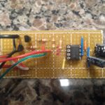
- Timer and transistor/switch board. My first time working with veroboard — will definitely use again!
-
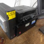
- Finished product next to radio and power supply
-
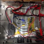
- Finished product with cable ties to enforce a layout among the wires