I’ve been playing with connecting an Arduino to an AD9850 DDS waveform generator. This is a DDS chip from Analog Devices that is capable of outputting a sine or square wave at frequencies up to 40 MHz. There are two variants of the popular low-cost boards available (such as on eBay) that provide a plug-n-play implementation of this device. While it is easy to find the documentation for the AD9850 chip itself, it is harder to find pinput/spec information about the board itself.
This post from NR8O’s website provides most of what I used to get up and running, including using his test code – I have the same device from eBay. This library may be useful in the future, which is an Arduino library for controlling the AD9850/1 chips.
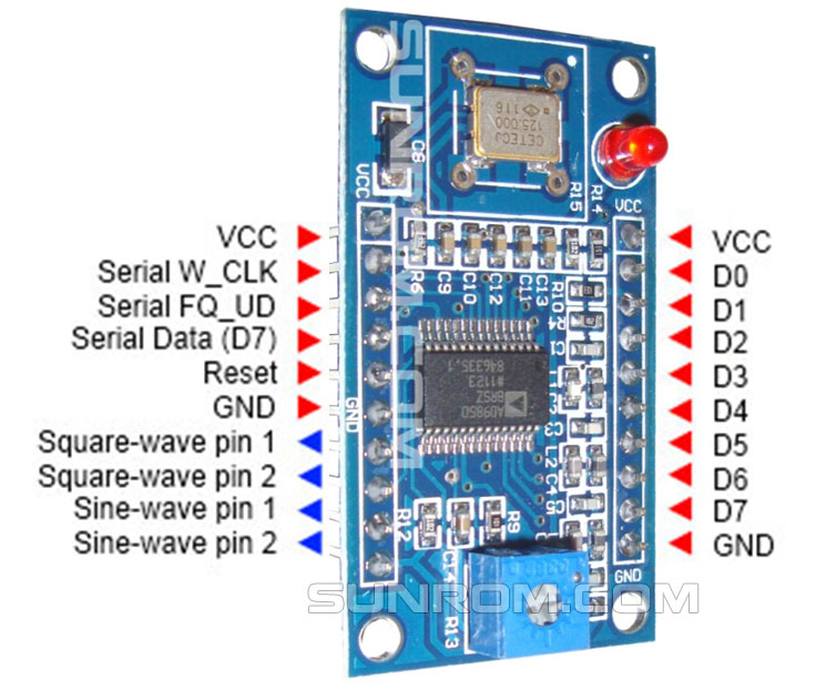
Here is one page with the pinout. A copy is shown above (in case it ever goes offline). From online reading, I believe the difference between the two sine and square wave outputs is the presence of a low-pass filter.
So how accurate is is? When running at 20 MHz, and looking at an auto-frequency calculation on my scope, every measure I pull up is within 10 Hz of the specified frequency, and usually less. This is not a statistical sampling, but suggests the DDS is pretty solid — a lot more drift would be visually noticeable on the scope.
It appears that SineWave1 is unfiltered, while SineWave2 is filtered. At lower frequencies (like 100 kHz), the Sinewave2 output was much cleaner (less spurious scope triggering), at higher frequencies, the waveform was clearly attenuated. In theory the output is a 1Vpp sine wave, with min/max voltages at 0V and 1V. Here is the output I obtain at different frequencies (these are not average values, but “eyeballed” from the instantaneous frequency measurement. My Digilent scope only samples at 100MHz, so there will be some error at these high frequencies). The DC value remained about 0.51V at all frequencies.
[table “” not found /]Further info on the output filter. At 1Mhz, Sin1 has its 1MHz peak at -10dBV, and the odd harmonics (not sure why just odd — crossover from the square wave generation?) have peaks at -50 dBV. The noise is at about -70 dBV. Meanwhile, Sin2 at 1 MHz has similar specs and a total lack of harmonics.
The square-wave output is 5Vpp in amplitude, and looks OK up to 1Mhz. It is harder to evaluate on my 100 MHz scope at higher frequencies (at 10 Mhz, that is only 10 samples/cycle) and there’s no cycle-triggered average feature. The square wave has prominent odd harmonics (base at 3dBV, 3MHz peak at -2dBV or so, 5MHz peak at -3+ dBV and even harmonics at about -40 dBV. For Square2 the even harmonics are not much more suppressed, but somewhat more at the 15+ MHz range. The pot on the DDS board is used to adjust the square-wave duty cycle — there does not seen to be a “digital” way to do it.
This makes me suspect how clean of a source this DDS chip may be for RF applications, but we will give it a try since others have.
Important specs on this board for future applications – output sine wave is only ideally 1Vpp, and output is limited to 10.24 mA with the 3.9K value of Rset on the board (I suspect that several designs using this chip online for impedance measurements ignore this fact).
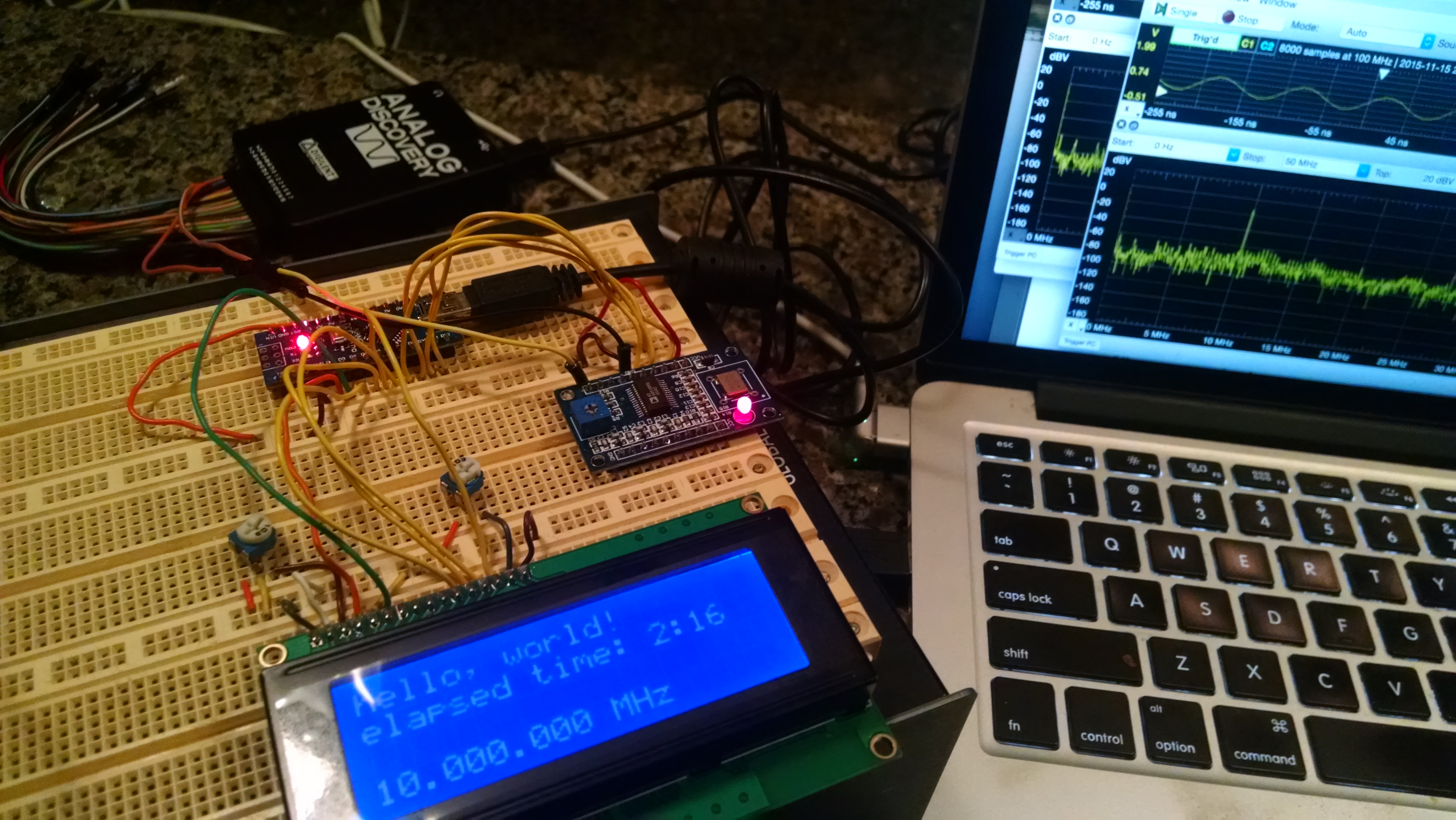
Below is a pic of the current setup with the Arduino Nano driving both an LCD display and the DDS9850 chip. I am running out of pins, but still need more for both the analog measurements from the analog circuit and the rotary encoder for making selections.
UPDATE: I finally found board documentation here, and here is a locally stored copy in case the original vendor link disappears.