Using a blog for debugging notes so I can easily refer to it.
LCD displays are quite common for Arduino applications. I have purchased a 20×4 white on blue backlit display. Most LCD displays on Arduino are based on a Histachi HD44780U controller chip, and the displays themselves have a relatively standard 16 pin interface. I am using a Chinese copy-cat Arduino Nano (ATMega 328), and it all works identical to the tutorial pinouts for a standard Arduino.
Things I have learned.
- The LiquidCrystal library (built in to the default environment) will likely handle all interface needs.
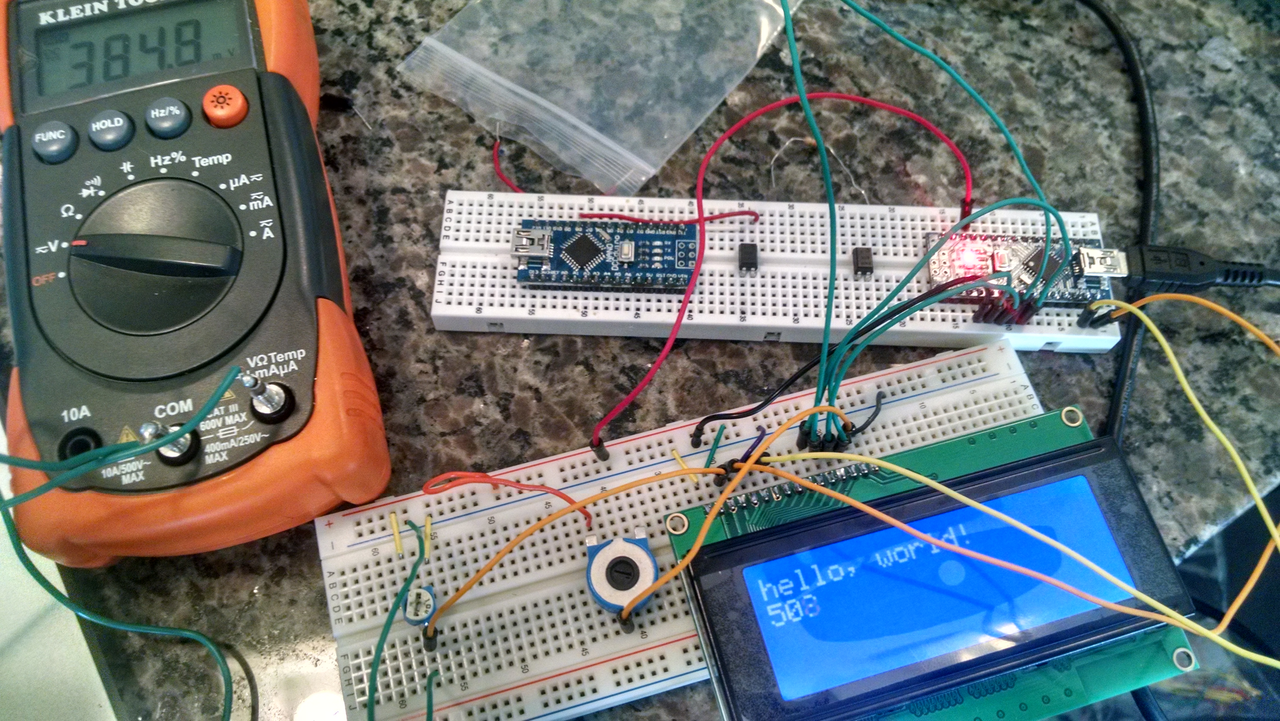
- Most examples use a pot between 5V and GND to provide a contrast control voltage, and a resistor from Bklt+ to 5V to fix the backlight. Examples online vary on what these values should be. Most say to use a 10K pot for the contrast — the datasheet suggests 50K to 100K, and heck, it will draw less power. I found a 100K pot works just as well as a with a 10K pot, and find the output voltage needs to be turned nearly all the way down to display the text. 0.7V output is barely visible, comfortable values are 0.4V to 0.3V (lower voltage is higher contrast).
- I still had trouble controlling the display backlight. The datasheet says to NOT connect directly to 5V (even though the Adafruit tutorial does so) — it may hurt the display, and it certainly may be a power hog! I connected another pot (22K, it is what I had) configured as a variable resistor, between Bklt+ and 5V. This provided excellent control of the backlight — the readable settings varied from 1.7K (barely visible) to near 0K (very bright) for this resistor. A downside of a white on blue display is the constant power to see the text — I think I would like a passive display with backlight next time. This pot is extremely sensitive — I think a 2K-5K pot would be ideal in the future, or use a 10 turn pot if you have something larger.
- I measured power consumption to the breadboard with the LCD display as I varied backlight settings. Super-crazy bright was 30 mA, while very readable and still quite bright was 4 mA. What a huge difference in consumption! A barely readable backlight was 2 mA of consumption. The contrast control has a minimal effect on power consumption. This likely explains why the datasheet says not to connect to 5V — there is visibly little readable difference between 4 mA and 30 mA.
- These displays require 4 or 8 data lines, as well as the serial (I2C) interface. It is possible to purchase variants of this display with a “backpack” chip set (soldered onto pads that already exist on the PCB in the back) that make it a true I2C device, with no data lines required. Other sites online have rolled their own using a 74595 shift register and a transistor. I need to keep this in mind since this is my first learning step in a project that requires both an LCD display as well as an I2C controlled DDS chip, and pins will be used quickly.
- I also do not know if the LiquidCrystal library is using the built-in Arduino I2C hardware or implementing the I2C/serial in software. In a perfect world I’d like both the DDS chip and display running off the same I2C bus to save pins. But I can tackle this on a future day.
- This is one of many steps in building an antenna analyzer … stay tuned (pun intended!)