SWR measurements of a SOTABeams Band Hopper

I am not yet a SOTA/POTA activator, though I would like to be (actually, I have one SOTA activation on 2m VHF). However, I do travel with my radio, and have brought my Kx3 on trips, along with a 20m end-fed and/or a load-coil with whip and tail antenna.

I have built and tuned over a half dozen antennas with home-made baluns, mostly dipoles and doublets, also verticals. My antenna at home is a fan dipole with separate 20/40/80 elements all tuned to 1:1 SWR. I wanted a linked dipole that was sufficient for 100W so I could use my home radio (the rig is in a luggable case) or my KX3. I made one for 20/40, but it was too heavy for my telescoping pole for portable use. After spending a lot of time trying to figure out the coax that is just good enough for 100W, the wire good enough, the smallest but most useful toroid, etc. I decided that I was reinventing something and SOTABeams had these details figured out! I likely could not make one for a lot less than what they charge, so I bought the 20/30/40/80 Bandhopper from DX Engineering.

I brought it with me on a trip to Florida a few weeks ago, went to set it up for use, and discovered that that one leg was broken (accidental cut? my packing fault?). Packed it up. The following week I fixed the broken link by tying a knot for a secure link, soldering the ends, and encased it all in heat shrink tubing.

A couple of weeks later, I decided to head to “the land” to measure this antenna. We own a 3 acre plot of land adjacent to a county park with a nice clearing on locally high ground. The nearest house is over 1000 feet away. It is like a private field day lot and ideal for operating, and I keep a tag line in a tree for just this reason. And a picnic table!

antenna test site

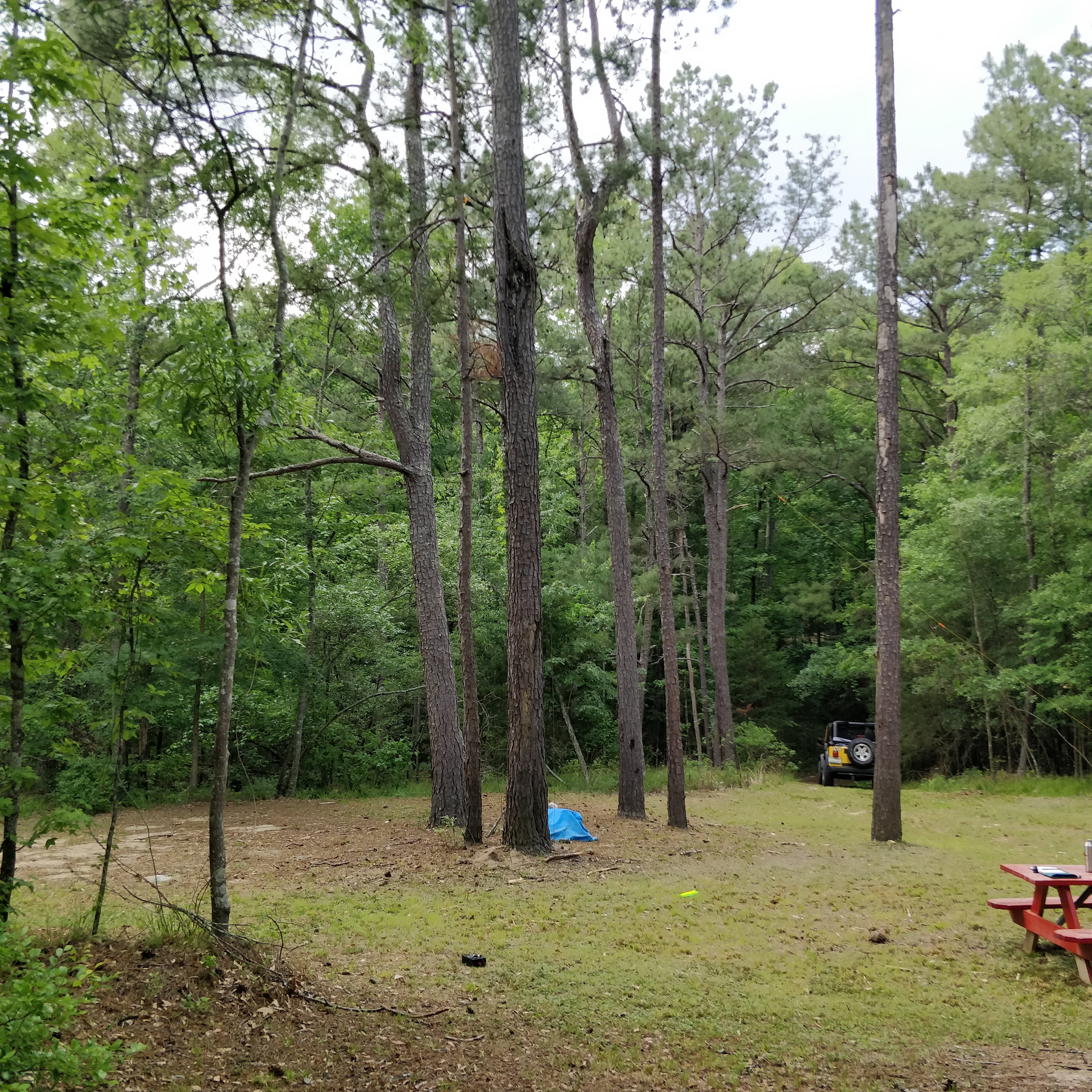
Antenna test site. Complete with picnic table! My Jeep is in the distance to keep it sufficiently far from the antenna.

I unlinked all of the links to measure the 20m response, and raised the antenna to a height for a 45 degree inverted V with the 40m ends about 3 feet above the ground. I know from my past antenna builds that distance to the ground matters (more on that later), but this was a good starting point. The 20m elements were 10-12 feet above the ground. Measurements were made with an MFJ-269 SWR meter.

To my surprise, at 20m, the antenna had a 1:1 SWR at about 14.700 MHz. It was similarly too high at 30m (10.432 MHz), and measured 1.1 SWR at 7.150 MHz on 40m. I wondered if the knot I tied at the break had something to do with it. My math said that a frequency this off likely required a lengthening  of each dipole leg of about 6.5″, but the wire associated with the knot was under 3″. I cut away the heat shrink tubing, replaced it with a crimp connector. and repeated. Still resonant on 20m at 14.560 MHz — still too high.

My experience is that ground effects matter with inverted Vs close to the ground. Maybe the SOTABeam was tuned for exactly this scenario, thinking about how a portable operator might operate in real world conditions.

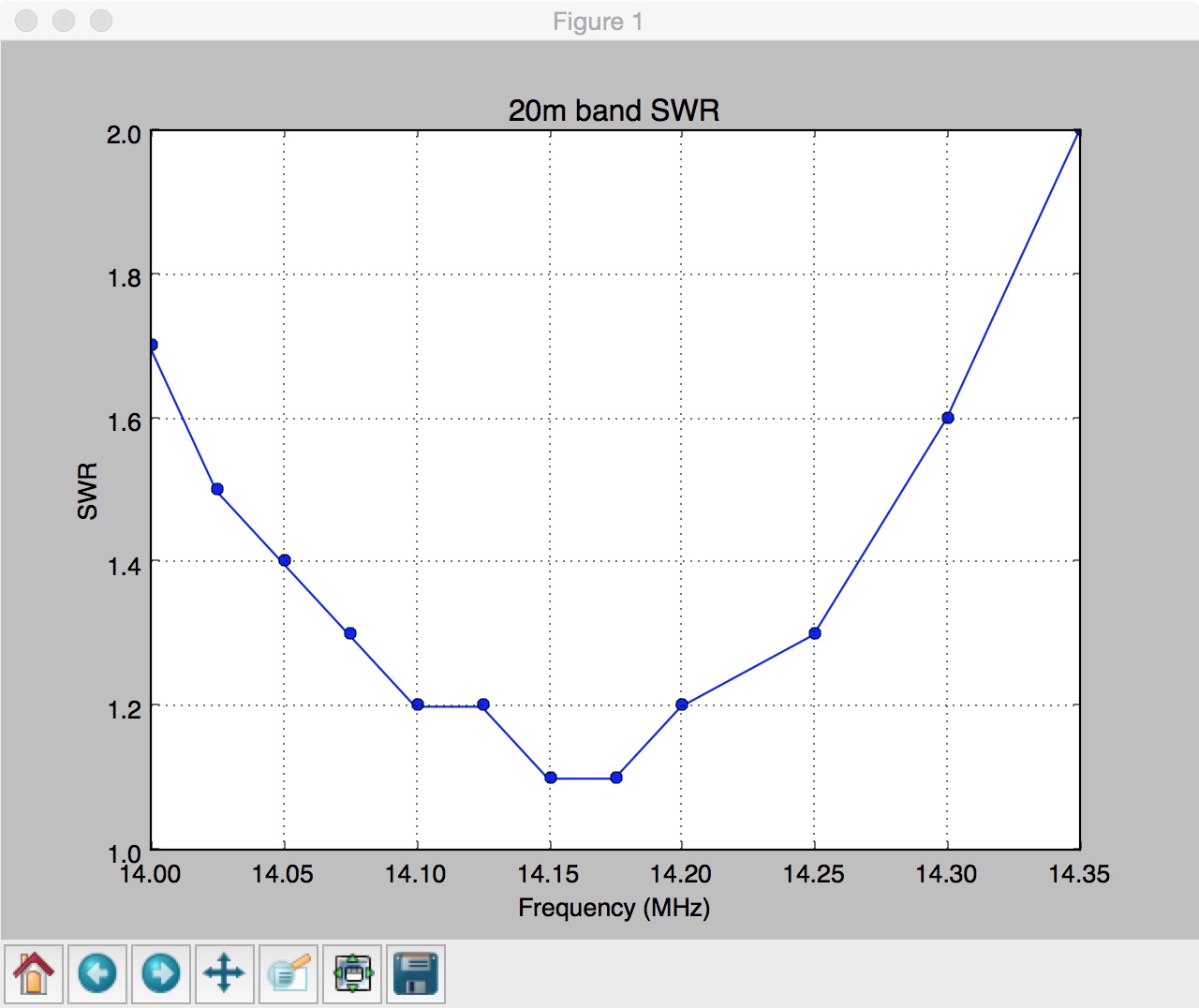
I lowered the height of the inverted V, still 45 degrees or so, so that the 20m ends were inches above the ground. I measured the following results for 20m:

20m SWR

Freq (MHz)SWR
14.0001.1
14.1051.0
14.3251.3

I continued this same process for 30m, 40m and 80m, adjusting height so the leads were within inches above the ground.

30m SWR

Freq (MHz)SWR
10.0001.0
10.1501.5
10.3002.0

40m SWR

Freq (MHz)SWR
7.0001.1
7.0401.0
7.1501.5
7.2662.0
7.3002.2

80m SWR

Freq (MHz)SWR
3.5001.7
3.5231.5
3.5891.1
3.6451.5
3.6902.0

I could have tweaked these by adjusting ground height, playing with the lead links (can clip upline or downline for minor lengthening and shortening). But my take-away from this is that the Bandhopper is very well tuned, and tuned for an inverted V at a height with the ends nearly at the ground, and optimized for the low end of each band. This makes sense given the prevalence of CW in SOTA operations, which is at the low end of the band.

Just for fun, I decided to see how well the antenna would work as a quick and dirty vertical. My experience with home-made verticals is that ground height from the balun matters, and radial length matters as well, especially if using few radials (like one!). I tested the vertical at 20m, 30m, and 40m with the “ground half” of the dipole linked to the same length and just coiled in a loose pile a few feet around the base. Optimal SWR in all cases was with the balun at the vertical base just above ground height. The SWR was 1.3-1.4 across the band for 20m, 1.6-1.7 across the band for 30m, and 40m ranged from 1.8 (7.000 MHz) to 1.5 (7.150 MHz) to 1.4 (7.300 MHz).

I ran out of time and did not measure the 15m response of the 40m dipole, but based on my experience with other 40m dipoles I would expect it to be quite usable with an SWR of less than 1.5.

In summary, I am impressed with many aspects of the design of this antenna. The winders are well thought out, and the materials used are as minimal as possible but good enough for the job. If I was doing SOTA activations, I would likely not deal with the added length of 80m and just buy a 20/30/40 or 20/40/60. That may be coming soon!

SYOTA.

Rob Butera KM4MK

Posted in Uncategorized | Leave a comment

IKEA couch spring repair

About a year ago we purchased and assembled an IKEA sectional sofa for our living space.   A few months later, we notice one of the springs under one of the cushions had sprung loose. And another. By nearly a year later, they all had (except one).

IKEA offers a ten year warranty. But that requires a receipt. People keep furniture receipts? And I would have to return that one section of the sofa.  So I figured I would fix it myself.

C-clamp to pull spring. C-clamp, shim, zip tie. Voila. Reassembled. Easier said than done — it requires a clamp with enough spread to grab the spring near the end, and enough travel of the screw to pull it back into the plastic clips. Wear safety glasses and gloves in case things go pop. Reassembly looked like below (this is actually a photo from later in this post, but you get the point).  The zip-tie is to stop the C-clamp from popping out the open side of the zig zag.

Or so I thought.  The next morning, all the springs had popped their plastic clips again.  What was going on? Take a look at this photo of the springs (below), taken shortly after reassembly. The Re-attached springs. At least for 12 hours ...reattached springs are on the left. The springs that did not pop are on the right.  What do you notice? They are not the same size springs. The springs on the left half are slightly shorter when untensioned, and if you look at the zig-zags, the ones on the left have a smaller curvature, and there is one more serpentine zig (or zag?) if you count the length on the left vs the right. All the other sections of my sofa have the springs on the right. In short, whether intentionally (they ran out?) or by accident, IKEA used a different and slightly shorter spring on the left, it over tensioned, enough to eventually bend the plastic clips along the front of the couch (where people land when they sit down) so that they no longer would hold the spring in place when faced with even a small amount of vertical movement. You can see on the left (if you expand the picture) how the plastic clips are over-stretched compared to the clips on the right.

The fix.  Upholstery clips. A bag of 25 purchased online.  Upholstery clip holding IKEA springAnd 1″ #6 pan-head screws. I removed the original plastic clips (twisted with pliers, cut with knife). I cut a 3/4″ piece of wood to shorten the stretch distance (see pic above) to what seemed right for the spring, anchored to the frame with wood screws.  Setting the height to match the springs on the other side was also important (and also for how the cushion sat on it). Tension with the C-clamp, align the clips, screw.  It is important for the screw angle to be perpendicular to the clip or pointing slightly into the bend.  If it points slightly away from the bend, it may not pull the clip tight (pulling the metal against itself) — ask me how I know!

The finished product. Ready to bounce!The finished product – left half has replaced springs. Note I did not replace the spring on the edge. That one did not spring loose, though the plastic clip was still bent. It would have required removing the piece of wood the leg is attached to in order to use the C-clamp. Since it did not spring loose, I left it along and also used 3 zip ties to attach it to the adjacent spring in case it did spring loose.

I re-assembled the sectional sofa and plopped down on the couch a few times for good measure.  It is holding!


Posted in Uncategorized | Leave a comment

Scout’s vigil and the beginning of the aftermath

Note: A friend asked if I’d share this FB post more widely.  I refuse to make it global on FB, as it would then invite the inevitable cesspool of comments if it was shared widely.  But feel free to link to this.   It was my experience tonight (Sept 18, 2017) at the vigil for Scout Schultz, on the Georgia Tech campus.

****

I was there tonight. I thought it was a subtle but appropriate event, and it gave students space to grieve. Kudos to the Student Affairs and the PRIDE students for what was organized. The administration, or at least the public faces students know (Deans, President, Provost) were notably absent. I saw a few of my colleagues (including a School Chair and Vice-Provost), and I’m proud of you for showing up. None were recognized, nor was it appropriate to do so — this was by and for students.

When it was over, hundreds stayed around, and started yelling, discussing, grieving. Anger was voiced at how we got to this place, anger at GT’s President, anger at a lack of sufficient counseling services. From there it digressed into what I would call generalized anti-establishment anger: rage against buildings, statues, the income of the President, rankings, etc.

I did not think it would get this bad. I found myself unwittingly in the middle of the protesters (at least, I suspect it was the group that started the protests) and I have one observation: as far as I can tell, these were not Georgia Tech students. Or very few at least. When the memorial event was over and people started shouting back and forth, those advocating violence were resoundingly shouted down by other students.

Then the drums and banner appeared out of nowhere, and the F-the-Police chants started. I’d estimate it was no more than 50 people. When the drums started, Tech students’ notable apathy for protest (or a desire to go back and study) was true to form. Students left at an increasing rate, many to the student center and the counselors therein. A lot of students just wanted to be left alone and grieve.

I walked to my car. I got home 20 minutes later when the GT Emergency Alert was sent out.

This is the worst thing to happen to my campus in a generation. Torching a car? WTF is wrong with you people?

Posted in Uncategorized | Leave a comment

RFID-activated High-Current Power Supply Switch

More details forthcoming.

Notes: 2N3904 transistors were replaced by ones with a much lower VCE voltage. The 220uF decoupling capacitor is critical to avoid odd slow powerup oscillations (likely due to relay inductance).

Schematic at EasyEDA

PDF schematic

The enclosure is a Hughes SatTV box I bought at a thrift store for #1, tossed the board, and saved the power supply for a future project.

What this does: allows an RFID reader to switch the power on a 12V power supply that sources about 20A.  An automotive relay is used to switch the output of the power supply. They keypad activates the relay, and the relay uses a latch configuration to keep the relay on after they keypad output goes low again.

This would be a very simple circuit if not for the fact that the keypad has a power-on glitch (output is activated for about a second), and the power supply whose output is switched is also used to power the keypad! The solution is to have two transistors in series switch the relay switch — one transistor is controlled by the keypad, the other by a 555 timer circuit that does not go high until about 7 seconds after power is turned on.

Finally, the switched output is also tied to a 12V automotive indicator lamp, to remind users that the power supply is on.  The entire system is turned off by just turning off the power supply.


Posted in Uncategorized | Leave a comment

Backslash line continuation in code comments

I spent several hours this weekend tracking down a bug that highlights something I never knew about GCC (and the Arduino IDE, which uses GCC). At first I was inclined to blame the limited Arduino IDE, but that in itself based on GCC. So I replicated the behavior using command line GCC on a the code below, on both Linux and a Mac.

Compile and run the following code in GCC:


#include <stdio.h>

int main()
{
printf(“Hello Line 1\n”) ; // this is a comment
printf(“Hallo Line 2\n”) ; // comment with back \
printf(“Hullo Line 3\n”) ; // This line will not print – try it!
printf(“Hillo Line 4\n”) ; // last line
}

Line 3 does not print!

As a long time UNIX user, I get what is going on — the backslash forces a line continuation — so line 3 is effectively considered part of the comment on line 2!

But why does GCC parse this way? C/C++ already doesn’t care about line breaks and continuations, since all parsing has well defined delineations.  In fact, // is an “exception” that doesn’t require a matching terminating delineation — it is the line feed.  But the norm is that it is only used for one-line comments.  Except I guess those one-line comments can be continued on the next line …

I came across this issue while editing/debugging a font set and display library for an Arduino display project. I am posting this in case someone else ever tries to google the answer.

Posted in Uncategorized | Tagged , , | Leave a comment

Arduino Class Sunday July 24 2016

This is a reference post for the Intro Arduino class I am teaching at Decatur Makers on July 24, 2016, from 6pm-9pm.   See the Decatur Makers website for cost and registration info.

Getting Started with the Arduino!

Low-cost user-friendly microcontrollers have made it possible for anyone to quickly create small electronic projects.  Many DIY projects use microcontrollers.  This getting-started session will introduce users to the Arduino system and provide hands on activities with a low cost kit of electronic components, as well as your own Arduino (open hardware clone) to take home.  

What we will (try to) cover:

Code for class (the LCD display uses the stock code from the LCD display demo)

  • LCD display will use the standard arduino.cc tutorial code above. CONNECT RW TO GROUND.  This is not stated, though shown in the diagram.
  • IF TIME — analog reading, using stock arduino.cc tutorial (AnalogInOutSerial) and we will modify to demonstrate plot monitor

What you need to bring — a laptop computer.  Windows, Mac, or Linux. Macs sometimes have problems with the drivers (see below).

What you will receive! — an Arduino Uno (clone), breadboard, ~20 jumper wires, ~10 assorted colored LEDs, assorted resistors (10 each of 220/1K/10K/100K Ohm), potentiometer, ~5 pushbuttons with caps, 16×2 LCD display

BEFORE the class

These Arduinos use the CH340 USB serial driver.  You need to install that driver on your computer.  Follow these instructions from Instructables.Com.

If you have not done this, please arrive at the class 45 minutes early.  Based on past experiences, it works fine for most, but there are always a handful of Windows and Mac computers where the installation requires some kicking of the tires.

Reference Material

http://www.arduino.cc is an excellent reference.  It contains an online reference guide to the language and programming environment, and explains each of the example sketchs (programs) built into the programming environment.

All the components in the kit provided are standard components used in many electronic projects.

Adafruit (http://www.adafruit.com) and Sparkfun (http://www.sparkfun.com)  are two common online companies to buy components and kits for microcontroller-based projects (such as LCD displays).  These companies also often have tutorials on their website for each of these components.  eBay is another place to buy many of these components — asian manufacturers often sell and ship direct for much less money than US or European manufacturers, with the tradeoff of a longer shipping time and unknown documentation.

Fixing Driver Issues

Some OSX users had trouble.  Seemed to be fixed by

Additional Code

Here is my sketch for a CW  (morse code) beacon/message sender.  (ZIP file) You can change the #defines for your desired words per minute and the outgoing text, and the program will loop and key the message at the interval specified in the code.

Posted in Uncategorized | Leave a comment

Tontec 480×320 touchscreen display with Raspberry Pi

Last December, I purchased a Tontec 480×320 touchscreen display for use with a Raspberry Pi.  Complete with case (amazon link).  I bought it along with a Raspberry Pi Model B in order to play with software-defined radio (SDR), motivated by the FreqShow example at Adafruit.  In fact, I wanted to get this example working.

But the display sold by Adafruit is not the display I bought, and I found a lot of online questions trying to get the Tontec display working with Raspberry Pi.  X windows applications worked, but the pygame library returned errors, and I tracked it down to the ability of the distribution I had installed to work with the graphics (not X windows) mode.

After several hours and lots of installs and reinstalls, the following two steps worked to get the Tontec display working.  Note that this was as of December 2015, and maybe jessie has changed by now.

Now the instructions of the example at Adafruit work.  I tried taking a short-cut and installing rtl-sdr from a package using apt-get — it did not work quite right.  The instructions on adafruit (download and compile from github) worked.

Tip: I don’t like the Pi automatically booting into X windows.  It is annoying.  You can disable it with sudo systemctl disable lightdm.service.  If you want to manually get X windows started, you can always run /etc/init.d/lightdm (start | stop) to do so.


Posted in Uncategorized | Tagged , | Leave a comment

Serial communication with a Kenwood TS-570D

I am setting up an amateur radio station at my local maker space, Decatur Makers.  Our transceiver is a Kenwood TS-570D.

I have spent a lot of time debugging how to get serial communications working between the Kenwood and a computer. Here is what I have learned. I have duplicated these results with two different computers (a Mac and a Linux box).

  • The Kenwood connector is male.  Odd but true.  You need a straight through female-female DB9 cable to connect to a typical 9 pin serial port.   Some gender adapters and female-female cables are configured as null modem cables, so be sure.
  • No handshaking or hardware/software flow control; BUT
  • The RTS (request to send) pin must be set high on the computer for the Kenwood to respond.  It will still receive commands if the RTS is not set, but not send responses.
  • The maximum baud rate that works is 4800 (8-N-1 or 8-N-2). Nothing faster worked.  Online forums confirm similar results.

When I do all the above, I can successfully open a terminal window and send CAT control commands to the radio.  If  you have never done this, these commands are the basis of amateur radio – computer communication for control.  Examples:

  • Send FA; The radio will return FA00007123456; — where the long number is the radio frequency in Hz.
  • Send FA00007121321; and the front panel of the radio will switch to 7.12132 MHz (radio does not display last digit, but it is stored)
Posted in Uncategorized | Tagged | 1 Comment

KX3 as a (good enough) antenna analyzer

So I am working on a DIY antenna analyzer/impedance meter.  But I need to validate my design against a known antenna analyzer.  I do not own one.

But I do — my Elecraft KX3 can calculate SWR.  If you know the menus, you can bypass the tuner, press/hold the TUNE button, and read the SWR. The Android app KX3 Companion does this to plot a simple 5 point SWR calculation (the author, Andrea Salvatore IU4APC, writes a lot of great Android amateur radio apps – see her KX3 companion page).

The KX3 has a mode where just about any button you can press or menu option you can change can be controlled via over its serial/USB interface.  So why not write an app?  So I did.  It took a lot of trial and error — reading the SWR from the display was tricky, as was the ordering of some of the command and picking an appropriate settling time.

Use of this Python script requires that the PySerial, ArgParse, and MatPlotLib Python modules are installed. Assuming you change the path to the serial device, I expect it will work on any platform (I developed it on OSX).  The final version is run from the command line but fully featured, and incorporates built-in band lists for the non-WARC bands plus 30m, and outputs a text list as well as graphical plots, with the ability to suppress either.

This program was updated by John Ogrem (WX0M, r2bqdnx@gmail.com), in November 2021. His edits reflect the addition of an “SW” command making it easier to read SWR from the KX3. The revised version is available here ->  kx3swr.py.   My original version is available at -> kx3swr-v1.py.

Disclaimer: this is freely distributed software, untested on your hardware, that will control your radio’s transmitter.  Use at your own risk!

Here is the command line help.

usage: kx3swr.py [-h] [-noplot] [-notext] [-waittime WAITTIME] b [b ...] positional arguments:
b band [band band ...] (choose 10 20 30 40 80 160) optional arguments:
-h, --help show this help message and exit
-noplot do not generate plots
-notext do not generate output text
-waittime WAITTIME change default settling time in seconds after each
measurement (default is 2.5 sec)

Here is the text output of a 20m sweep of my B&W AP-10 (whip with load coil and counterpoise) and the resulting plot.

$ ./kx3swr.py 20
running sweep for 20mband 20m
14.0 1.7
14.025 1.5
14.05 1.4
14.075 1.3
14.1 1.2
14.125 1.2
14.15 1.1
14.175 1.1
14.2 1.2
14.25 1.3
14.3 1.6
14.35 2.0 20m SWR plot creation

swr20m

The SWR can only be read to one decimal place, since it is extracted from the display of the KX3 itself.

Future plans include another command line option to sweep a start and end frequency with a specified increment.  I have never used ArgParse before, but it makes command line parsing and documenting really easy. Now that I know how the serial stuff works, I’d like to put this on a microcontroller system to take into the field with me.

I have learned a few things by having this.  For example, I operate QRP from a condo with a whip and load coil on my balcony.  I usually set the coil lead by listening to the volume, and there are usually two adjacent windings that sound about the same.  From this analysis and running some sweeps, I learned that one winding of the coil changes the resonant frequency by almost 400 kHz, and that moving the lead a 1/4 turn can shift the resonant frequency by 100 kHz.  So picking the right tap by ear alone might only get me within +/- 400 kHz of my desired resonant frequency. I also learned the importance of counterpoise length and positioning.  The above is the best case after some playing with the counterpoise and lead tap location. The KX3 has a great tuner, but a more efficient antenna is a more efficient antenna, especially for transmitting QRP!

Theory of operation: For those who are curious, the general logic of the program is as follows:

  • saves your frequency and operating mode
  • puts the antenna tuner into bypass
  • for each band
    • switches to that band and the initial frequency in the list for that band
    • sweeps a range of frequencies, and for each frequency
      • measures SWR by the TEST button, turns off transmitter 2.5sec later
      • extracts SWR from the display reading
  • restore original frequency and operating mode
  • return tuner to auto-tune
  • print output
  • plot output

This program required a lot more effort than the finished code might suggest.  There was a lot of trial and error using the KX3 Utility in command mode and sending commands, figuring out how the KX3 responded.  Sometimes order and timing matter.  Something theoretically straightforward like reading the SWR from the display turned out to be surprisingly odd. The KX3 Programmer’s Reference was a critical reference for all of this, and many thanks to Elecraft for publishing such a document.

Posted in Uncategorized | Tagged | 1 Comment

I2C LCD Shield for Arduino – save wires!

The standard character-based display used on many Arduino projects are based on the Hitachi HD44780 chip.  They are available quite inexpensively, as little as $2.59 on eBay shipped from China for a 16×2 display.  Sizes go up to 20×4 (what I usually buy), and common modes include black on green, some with backlight, and white on blue, which requires a backlight.  These displays are supported by the native LiquidCrystal library built into the Arduino LCD.  Using these displays requires, at a minimum, 6 data pins, on the Arduino.  That can eat up a lot of data pins if you are using other items.

I2C to the rescue!  I2C is a 2-wire serial communication protocol also natively supported by the Arduino.  For a little extra money, you can purchase I2C displays with a “backpack” attached that reduce the display down to an addressable I2C device, and all is needed is a clock and data line attached to pins A4 and A5.  You can make your own with shift register.  You can also purchase the backpack separately.   Several exist, based on a variety of chips. The most common (and the subject of this post) are based on the PCF8574 (and variants PCF 8574A and 8574A) I2C shift register.

In theory, all you need to do is:

  1. Connect power, ground, and the two wires
  2. Identify the I2C address of your display
  3. You are up and running!

In practice, #2 and #3 are a time-consuming trade-off.  Identification of the I2C address is not hard — if not provided by the vendor, there are many Arduino sketches out there that will scan your I2C bus and identify the address of any device that responds — it has worked on the 3 I2C devices that I have.

The hard part, and the reason I am writing this blog post, is the frustrating aspect of finding the right library to use, and the correct pin configuration for your particular LCD backpack.

If you purchased your backpack from a vendor like Adafruit or Sparkfun, they have a library on their website.  And it will work, and they will help you (as well as the online community).    The downside of these libraries is that they make affect your use of non-I2C LCD displays.

If you purchased your I2C LCD display or backback from a cheap vendor on eBay or Amazon, you (like me) likely have no documentation.  Not only is the address unknown, but the exact configuration (what pins on the shift register are connected to the LCD display, issue with how the enable and backlight are configured, etc) varies from manufacturer to manufacturer.  To make it more complicated, there are MANY LCD I2C libraries out there, and they vary in terms of how much they give you controlto specify these pin configurations vs making assumptions.

I got to a point where my display was powered and visible to the I2C scanner, but various libraries I tried were not working.  I probed the pin connections and verified there were no bad solder joints, and I even bought a 2nd LCD I2C display to compare (different vendor) and had similar problems. I became convinced that the problem was getting the library to match the exact pin configuration between the 8574  chip on the backpack and the LCD display, and a few assumptions about other LCD pins.

I found a solution.  It works!

I highly recommend using this LCD library.  I like that it covers all possible displays and interfaces, but it also retains sufficient flexibility to change the pin configuration to work with your display. It is also well-documented and actively maintained. It replaces the native LiquidCrystal library in the Arduino IDE, but works fine with my non-I2C displays.  The only downside, at least on my Mac, is that by replacing a built-in library, it means any upgrade to the IDE means re-replacing the library.  Installation is a bit tricky, but this is true for most replacement Arduino libraries.

I also highly recommend reading this post.  This post identifies 3 common variants of the 8574 backpack, and how to configure the aforementioned library to work with each variant.  My two displays were of the #3 variety on that page, and that is what ultimately worked for me.

Once your backpack is working, I recommend you also read my blog post about using a potentiometer to control the backlight power.  The jumper on the backpack just turns the backlight on and off.  Putting a potentiometer between 5V and GND and using the wiper to control the display backlight can reduce current draw from 30 mA to as low as 4 mA with no loss of readability.

Ultimately, this is a tradeoff of time and money.  You can pay a lot less on eBay, Amazon, Alibaba, etc for a low-cost display, and devote some time to getting them to work (and you may learn something, too!)  Or you can buy something from a company like Adafruit or Sparkfun, use their provided libraries, and be up and running.  You will pay more, but it will work out of the box (you hope).  For me personally, I wanted a particular display configuration they did not sell, and I found their libraries more limiting (although they work with what they sell!) than several of the open-source libraries out there.

I am somewhat surprised, given the utility of I2C devices, that there is not a more consistent standard for I2C LCD displays (this would not be hard), enforced by built-in support to the Arduino IDE LiquidCrystal library.  At least, that is what I would do if I controlled the IDE development 🙂

These are really notes to myself, but I hope someone finds them useful.  For reference, here are links to the displays I actually purchased on eBay and Amazon.

eBay 20×4 LCD I2C display white-on-blue – $8.49 (including shipping)

Amazon 20×4 LCD I2C display white-on-blue – $5.49+$2.49 shipping

I particularly like the eBay vendor frentaly since they offer prices similar to those shipped from Asia, but are located in the US in an Atlanta suburb, so shipping is quite fast! (especially since I live in Atlanta).  Not a paid endorsement — I just like their prices and location due to fast shipping. I cannot speak to product quality beyond this display and another I2C backpack I have purchased.

Next up — I am trying to figure out how possible it may be to configure one of these I2C interace boards to work with an ADS9850.


Posted in Uncategorized | Tagged | Leave a comment